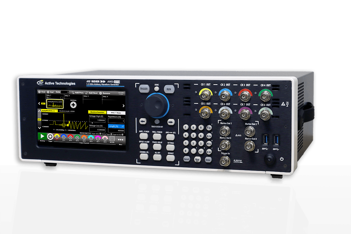
AWG-4000 Pulse Pattern Generator for Semiconductor Parametric Characterization
AWG-4000 Series Serial Data Pattern Generator (SPG) is a true Pulse Pattern Generator and it’s really useful to characterize standard logic gates and other generic digital systems. This Pulse Pattern Generator instrument simplifies the multilevel pulse generation thanks to its features, that combine the pulse and edge shaping with the ability to reproduce a multilevel programmed pattern. Considering the amplitude of 12 Vpp into 50 Ohm (24 Vpp into open) joined to an analog shift of ±6 V into 50 Ohm (±12 V into open) and the maximum symbol rate of 300 Mega-Symbols per second, this instrument finds application also as a replacement of discontinued products like the Agilent 81110A series.
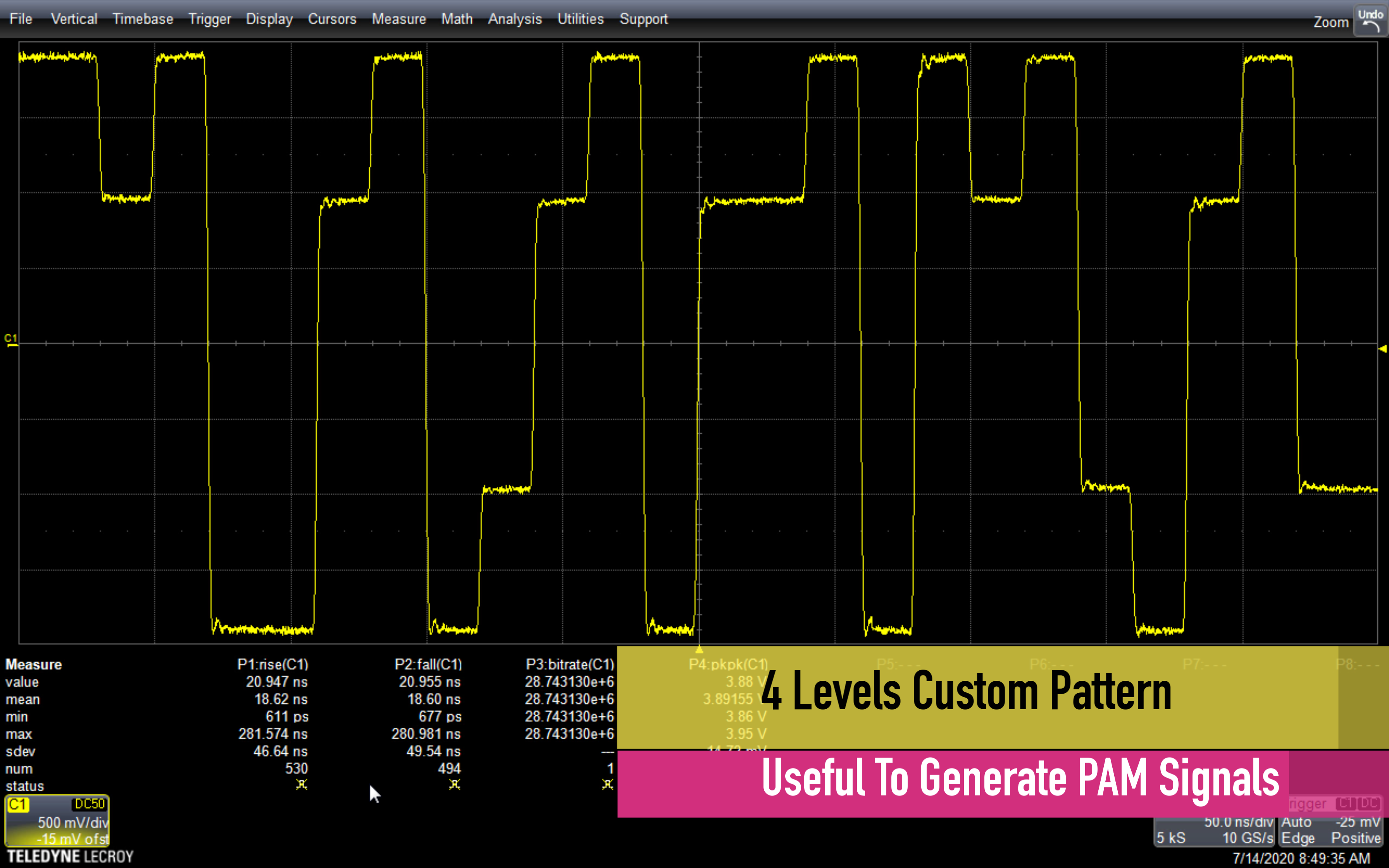
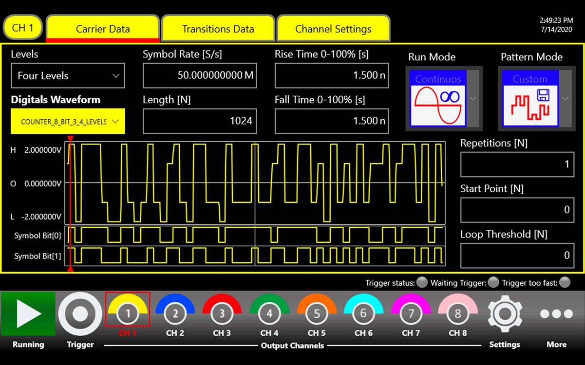
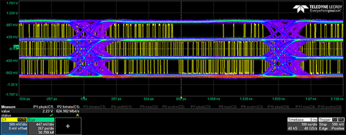
Up to 4 logic levels
For each channel it is possible to define up to 4 independent voltage levels to emulate, in addition to logic ‘0’ and ‘1’, a tristate buffer or a weak ‘0’ signal when a bus is not driven.
Edge Definition
The shape of each transition between the levels can be arbitrarly defined by the user. You can use this feature to shape the edge as RC transient or to add a positive overshoot. The 14 bit DAC
resolution and the 318 MHz analog bandwidth provides you an excellent signal fidelity.
Amplitude
The AT-AWG-4018 Serial Data Pattern Generator can reach up to 12 Vpp amplitude into 50 Ohm (24 Vpp into open); furthmore it is available a programmable hardware offset (called baseline offset) that allows shifting the voltage window of ±6 V into 50 Ohm (±12 V into open). In this way by using the baseline offset, the instrument can generate a 0 – 12 V signal into 50 Ohm (0 –
24 V into open).
Multi-Instrument synchronization: up to 32 channels Pulse Pattern Generator for Semiconductor Parametric Characterization
Each unit has 8 independent analog channels and it is possible to synchronize up to 4 units to build a 32-channels system.
Generation Modes
• Continuous: the generation starts when the user presses the Start button and it ends when the user presses the stop button.
• Burst: the instrument waits for a trigger and then the pattern is generated for the selected number of times. At the end of the burst the instrument waits for a new trigger.
• Modulation: the instrument applies a AM, FM, PM, FSK or PSK modulation to the generated pattern.
Fine time resolution
Thanks to advanced signal processing, the skew between the channels can be controlled with a resolution in the order of 1 ps.
Standard Logic Gates
Standard logic gates are the basic logic blocks that compose all the digital circuits. Although nowadays the development of digital applications is realized through programmable IC
such as MCU (MicroController Unit) or PGA (Programmable Gate Array), the discrete gates still find applications when the designers need a function that can’t be realized directly in the programmable IC or if the application is not enough complex to include a programmable IC on the board.
In some cases, it is necessary to add external logic gates to reach a bit rate that a programmable device can not support or to insert a level shifter to allow the communication between IC with
different voltage standards or to insert a multiplexer to increase the number of pins of a MCU.
There are many types of devices from different logic families (TTL, CMOS, BiCMOS, etc.) with the same logical function. To characterize and test them, from the simplest ones such as the single gates (NOT, NAND, NOR, and so on) to the more complex ones such as multichannel latches and counters, it is necessary to generate signals with specific characteristics in term of edge shaping, overshoot, amplitude, etc. Indeed it is necessary to remember that the digital signals are not ideal, but since we are in the real world, they take a bit of time to switch and can be affected by overshoot, so the right test signal is an analog signal that allows you to test a specific feature. For all those applications, the AT-AWG-4010 Series Serial Data Pattern Generator is the perfect
solution, because you can combine the digital pattern with the analog characteristics like edge shaping, amplitude, noise, modulation of the analog front end.
In the following section we will illustrate how to generate the signals needed for the digital tests with the Pulse Pattern Generator, as example we report a typical application.
Intuitive User Interface
The user interface allows you to easily program the instrument, using the touch screen and the physical keyboard. If you need to integrate the instrument into an automatic testbench, the AWG-4000 Series Data Pattern Generator can be controlled via SCPI commands.
Visit the Serial Data Pattern Generator page:
or take a look at demo video below.
Ferrara – Italy, May-28, 2021


