Pulse Generator Basics
PG-1000 Series Application | General Description
Pulse Generator Basics
This article describes basic operation of PG-1000 Pulse Generator
Transition Time
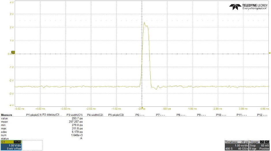
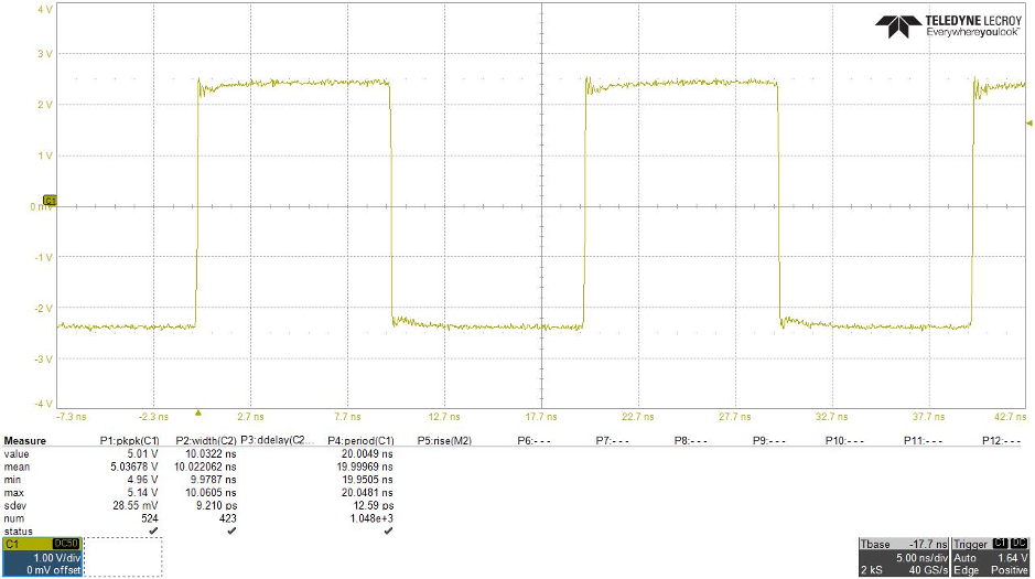
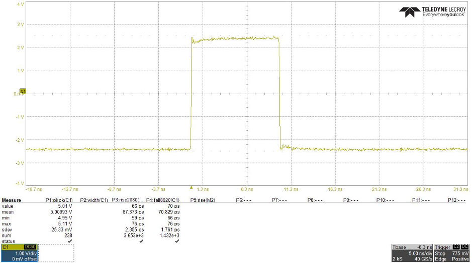
Pulse Rider PG-1000 series offer a rise / fall time less than 70 ps (20-80%) at 5 Vpp into 50 Ω with fully adjustable output voltage.
Min Pulse Width and Resolution
The pulse width can be adjusted from 300 ps to 8 s with a resolution of 10 ps responding to the needs of the most different applications.
Time Resolution
The delay resolution is 10 ps allowing a very fine adjustment between the trigger in signal and the generated pulses.Jitter is an important characteristic of the pulse quality, and low jitter in a clock waveform is an important feature in reducing error in communications systems.
The low jitter below 25 ps allows a perfect synchronization among channels and among multiple pulses of the same channel.
Trigger Mode
- Continuous: in continuous mode, the output channel supplies the pulses configuration at a repetition rate up to 125 MHz;
- Single: in single mode, the outputchannel waits for the trigger signal then it generates the pulses configuration only once;
- Burst: in burst mode, for each trigger received, the output channel repeats the pulses configuration a programmed number of times between 1 and 4294967295;
- Gated: in gated mode, the output channel supplies the pulse configuration only when the trigger is “true”, if the trigger becomes “false”, it continues the generation until the end of the pulses then it stops.
External Width (square / amplify external pulse)
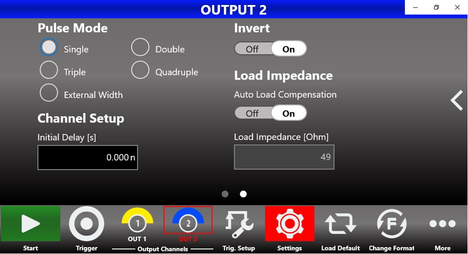
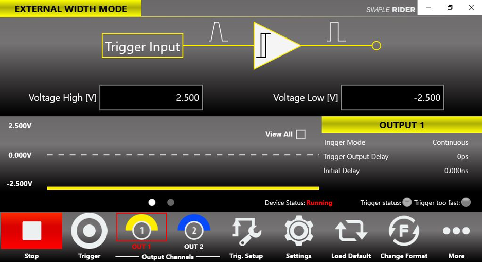
The external width operation mode transmits the Trigger Input signal to the output channel. This feature allows to make edges stepper than those of the source taking advantage of the RIDER Fast Edge technology.
Furthermore it can be used to amplify / reduce the amplitude, invert, apply an offset to the source pulses or to generate a particular pulse pattern sequence.
Pulse Combination (quadruple mode pulse)
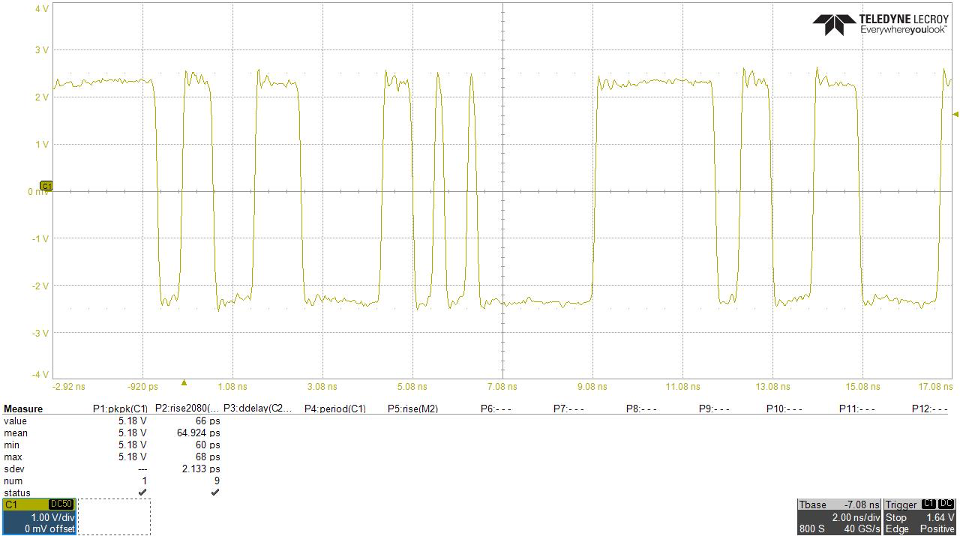
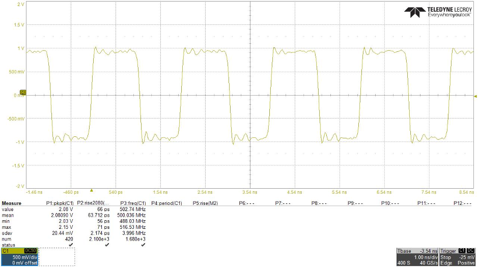
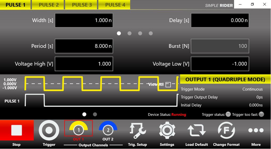
Using the multiple pulse combination to generate quadruple pulses, it is possible to reach an output signal frequency of 800 MHz that can be used to supply a clock.
Skew between Channels
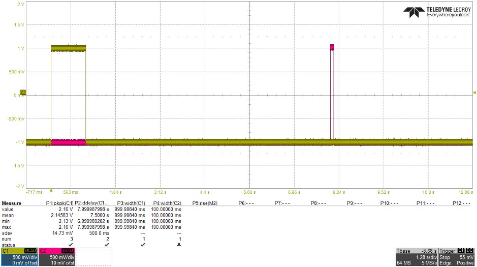
Every pulse can be delayed up to 1 s with a resolution of 10ps from trigger signal by setting the channel delay and the pulse delay parameters, the total delay of a pulse is: output N delay + pulse P delay + fixed delay.
This skill allows to produce an accurate skew to synchronize other test equipment compensating instrumentation skew, or to test the response of a digital asynchronous system at the arrival of not synchronized pulses.
Single Ended / Differential
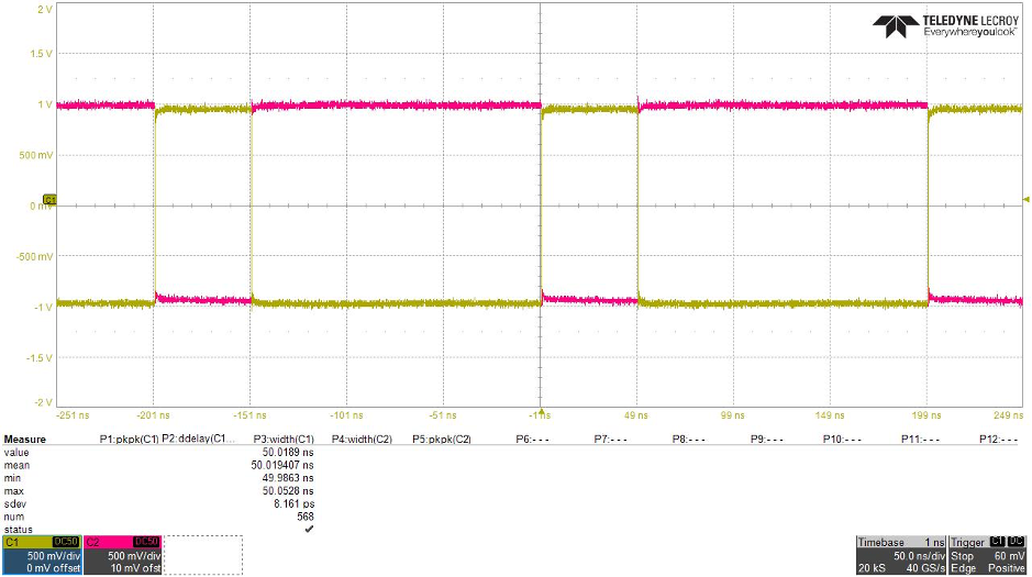
By using one channel as opposite of the other, it is possible to obtain the differential operation mode.
