Avoiding Phase Discontinuity in Arbitrary Waveform Generators
True-Arb Software | The Parametric Waveforms
Introduction
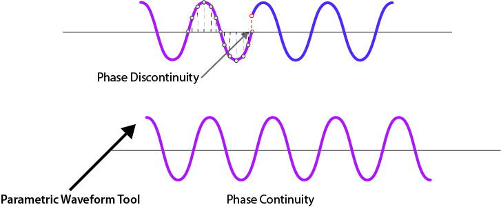
The most common arbitrary waveform generation use case is to play back a waveform that is finite in length and repeat it continuously. Although often overlooked, a phase discontinuity between the end of a waveform and the beginning of the next repetition can lead to periodic spectral regrowth and distortion. This problem is also known as waveform discontinuity as described in this article.
The phase discontinuity produces a noticeable increase in distortion components in addition to the line spectra normally representative of a single sinewave.
Another typical usage of an arbitrary waveform generator is to reproduce the waveform’s points at a precise frequency that it is constrained by the number of points and by the sample rate. For this reason it’s common to use a spreadsheet to calculate the exact parameters to match the desired output frequency.
The two tasks described above are very time consuming and moreover they can lead to different kind of errors.
For all these reasons and more, Active Technologies True-Arb AWG software recently introduced a new unique feature called Parametric Waveforms.
The Parametric waveforms simplify and speed up the creation of custom waveforms and now you can generate easily and in a flexible way, the signals for the most demanding applications, avoiding phase discontinuity.
While the AT Waveform Editor is still available, the parametric waveforms bring to the user’s tool palette, a new set of highly customizable, ready to use waveforms.
The Parametric waveform feature is part of the standard software package of all the Arb-Rider Series instruments, with no additional cost needed.
The Parametric Waveforms
The True-Arb AWG software lets you to create an Analog/Digital waveform in three different ways: importing the waveform’s points in txt format, using the AT-Waveform Editor or adding a New Parametric Waveform.
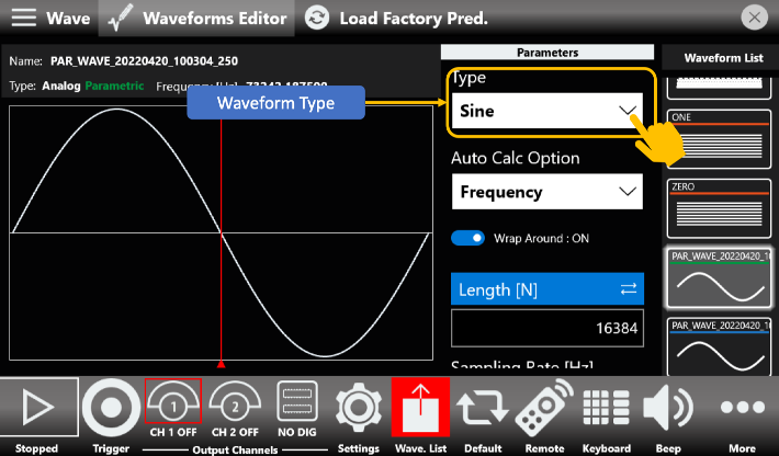
Once the new parametric waveform has been created, the page above will be opened. From here, you can select different types of waveforms by interacting with the Type drop down menu list. The available types are: Sine, Square, Pulse, Sweep, Sinc, Exp, PRBS and Multitone.
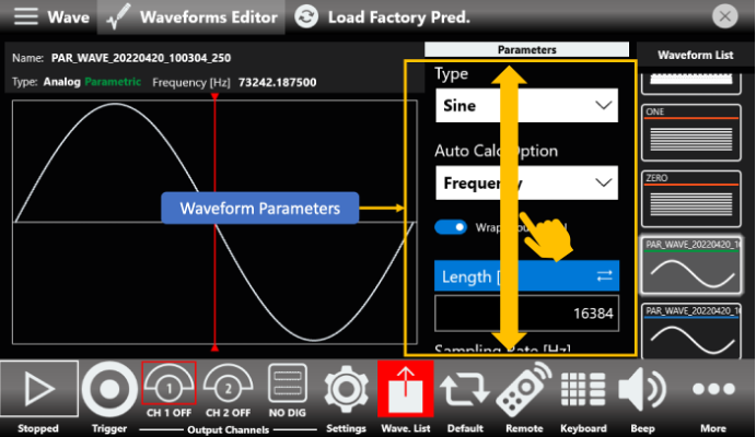
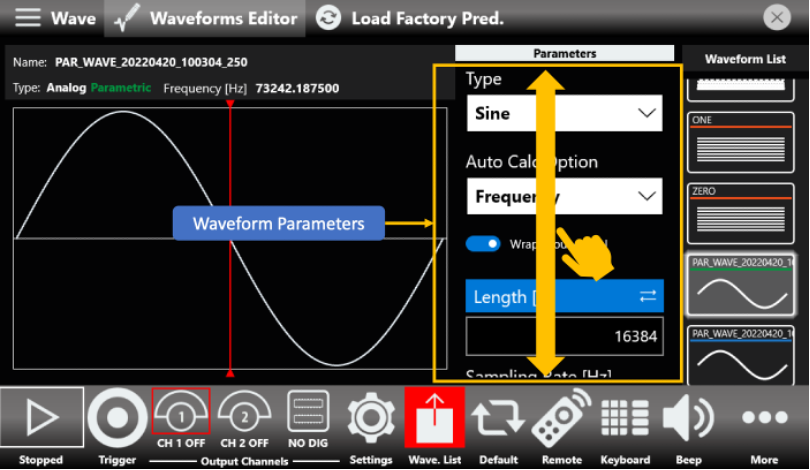
When you have selected the waveform you need, you can start customizing it. To do that, you need to set the characteristic parameters of each waveform type, which can be easily accessed by scrolling up and down the waveform parameters area as shown in the following image.
Auto Calculation of the Parameters
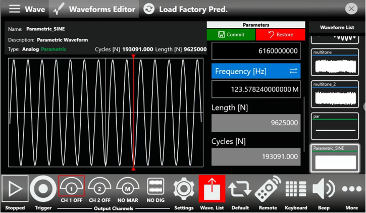
When you use an Arbitrary Waveform Generator, the frequency of the signal you want to generate is calculated by the equation that has as parameters the number of points and the sampling rate.
For example, if the sampling rate is 5 GS/s and the length of the Sine waveform in samples is 1000, the output period of the generated signal will be: 1/Fs * Number of Points, so in this case it will be 200ps * 1000 = 200 ns.
The frequency of the generated sine will be: 1/200 ns = 5 MHz.
The usage of the parametric waveforms allows you to skip the time-consuming task of finding a setup which correctly synthesizes the desired frequency.
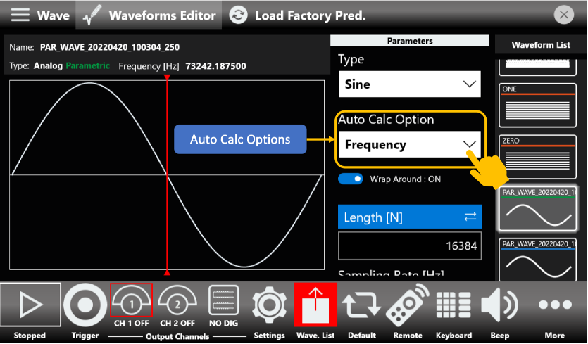
There are four Auto Calc. different strategies, with varying degree of freedom: length, sampling rate, cycles, length & cycles.
Lastly it is important to note the impact of the Wrap Around toggle switch.
When it is on, it forces that the number of cycles must be integer, instead, when it is turned off, the number of cycles can be not-integer.
It is a very important option given to the user, because a not-integer number of cycles can lead to undesired signal behaviors, like a spurious signal once analyzed in the frequency domain or phase discontinuity in the time domain.
Pulse Parametric Waveform
Nowadays pulse waveforms are highly important for experiments related to Advanced Research, Quantum, laser & photonics, radar & lidar testing and semiconductors.
It can be time-consuming calculating the right pulse for your experiments, because usually you should use an external tool like Matlab, Python or Labview to calculate the different parameters that involve a pulse signal like period, width, rise and fall time, duty cycle and amplitude.
Using a third-party software, you should export the point in txt format and then import them in your AWG software.
Active Technologies simplified that process by first introducing the AT-Waveform Editor, an integrated application that allows you to generate very complex waveforms and later the introduction of the Parametric Waveforms allows you to easily and fast generate the most advanced pulses for your application and avoid phase discontinuity.
Once you’ve selected “Pulse” from the list of available waveform types and selected the desired frequency, it’s time to start customizing it.
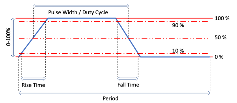
A Pulse parametric waveform, offers the following parameters related to the shape of a pulse: Fall Time, Rise Time, Pulse Delay and Duty Cycle or Pulse Width.
You can change between Duty Cycle and Pulse Width anytime by simply tapping on them.
A Pulse type parametric waveform abides by the following model:
Both Rise and Fall times follow the 10-90 format and are taken into account so that the above model holds true.
With Pulse Delay you can control the initial delay you want to apply to your signal.
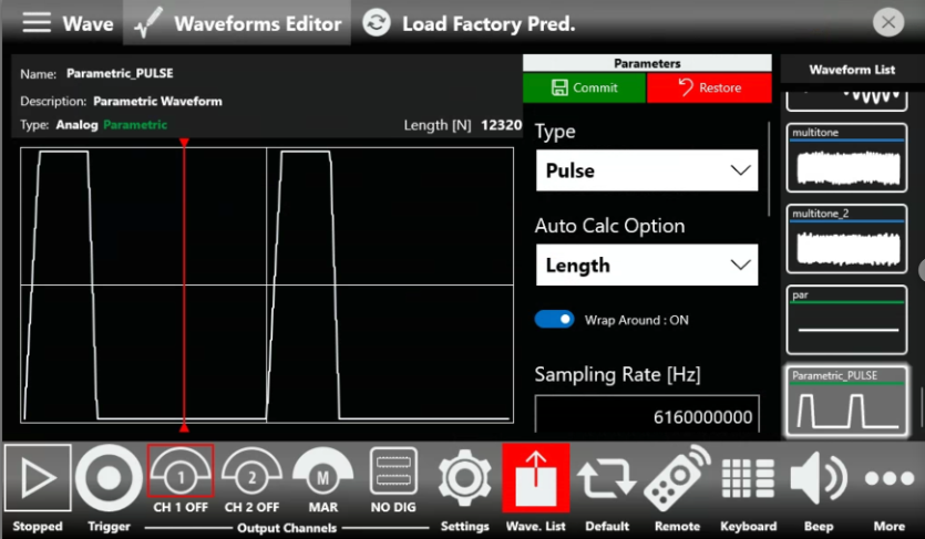
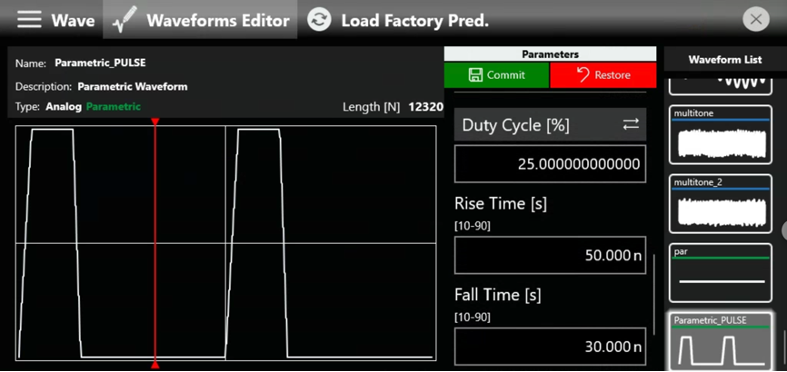
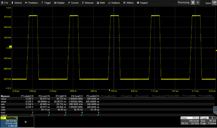
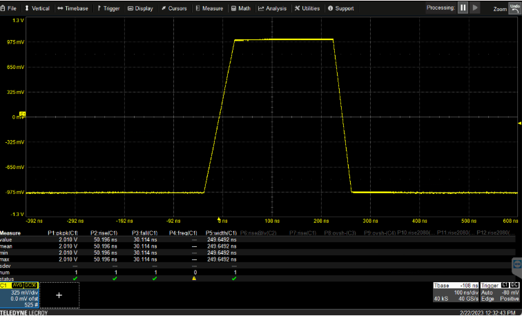
In the following example, we are creating a Pulse madse of 2 cycles, duty cycle 25%, rise time of 50 ns and fall time of 30ns.
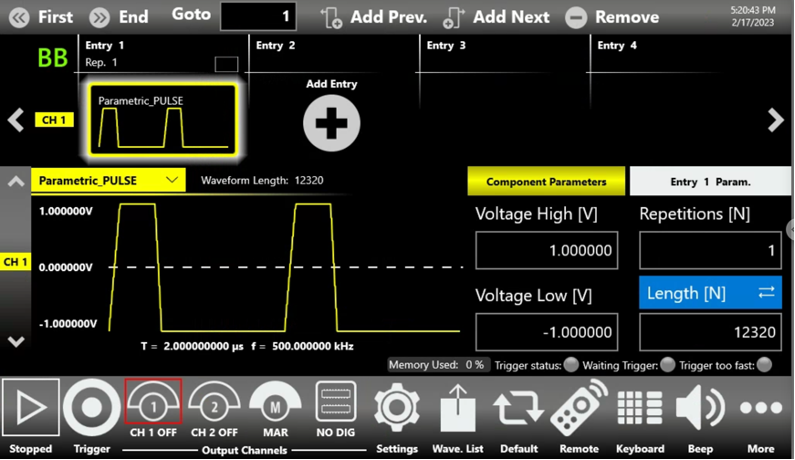
The Parametric Waveform tool automatically calculates the length of the pulses and the result is 12320 samples.
Once the Parametric Pulse waveform is ready, it is possible to insert into the sequencer and starting to generate the signal by pressing the Run button.
Multitone Parametric Waveforms
Multi tone signals are composed of multiply single sine waves or tones with a unique amplitude, phase and frequency. In the spectrum domain, the multi tone or RF energy will be present at a unique frequency. In the time domain, the multiply signals or tones will be a composite signal in which each of the tones will add or cancel to make a composite signal.
One area in which multi-tones are used is modern audio measurements to test consumers & professional audio devices, broadband devise and internet audio. Multi tones can be used in an open-loop audio test where the analyzer does not have to sync up with the generator.
Multi-tone tests are part of many test specifications used to test the frequency response of a device and measure intermodulation distortion. Two Tone and multi tone signals are used in the communications industry to test for nonlinear distortion for amplifiers, receivers, etc.
- Antenna resonant frequency measurement and testing
- Amplifier linearity
- Amplifier frequency response
- Selectivity measurement
- On-site effective sensitivity test
- Cable fault detection
- Filter tuning
- Antenna response to FM
- Frequency hopping
Multi tone testing is usually required in every terrestrial and satellite- communications application.
In modern days, not only VSGs can be used as Multi-tones generators, but also the AWGs provide great advantages on creating those kind of signals.
The Parametric Waveforms tool has a built-in type that speeds up the multi-tone generation avoiding phase discontinuity.
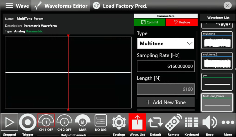
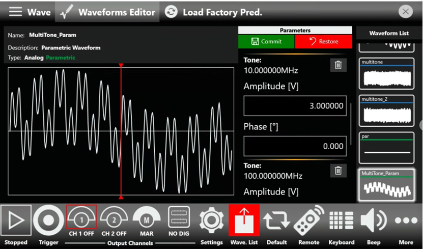
When you select “Multitone” in the Type dropdown list, you can start inserting the tones you need.
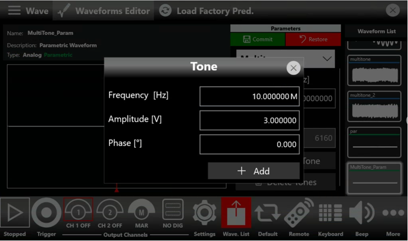
Press the “Add New Tone” button to insert the first tone and select 10 MHz sine wave with 3Vpp amplitude.
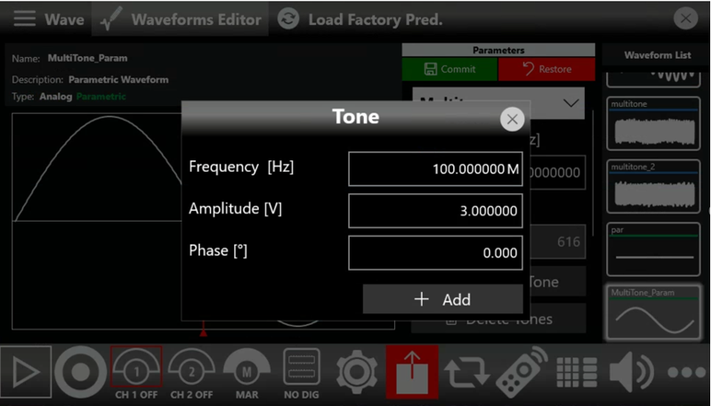
Press the “Add New Tone” button to insert the second tone and select 100 MHz sine wave with 3Vpp amplitude.
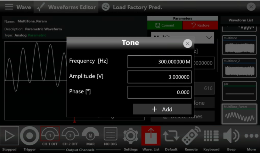
Press the “Add New Tone” button to insert the third tone and select 300 MHz sine wave with 3Vpp amplitude.
Press the Commit button to save the MultiTone_Param and it will be inserted in the Waveform List.
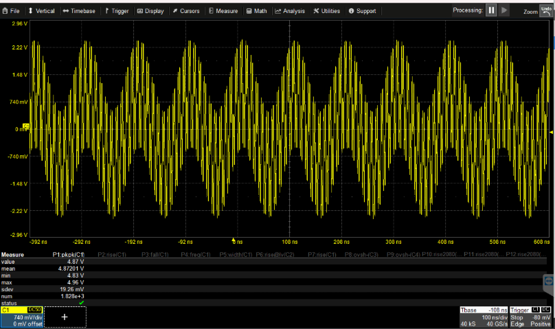
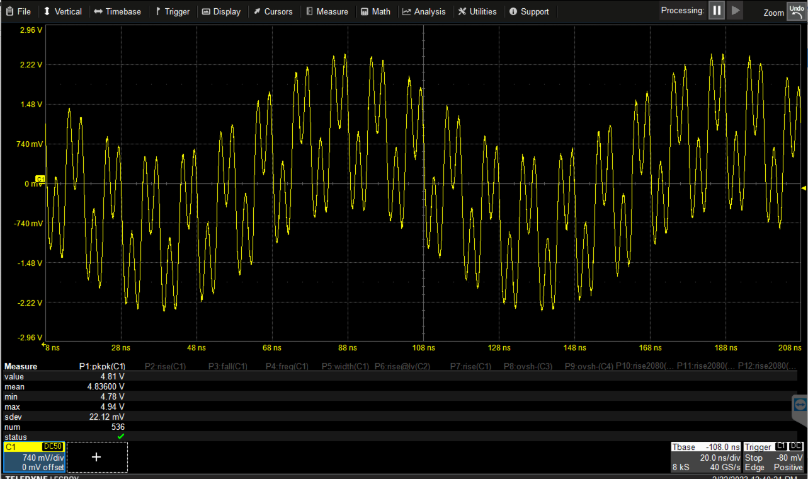
Now it is possible to add it into the Sequencer and start the generation.
