AWG to control Electro Optic Modulator
AWG-5000 Arbitrary Waveform Generator Application Note
What is an Electro Optic Modulator used for?
Nowadays the applications based on optics, photonics and pulsed lasers through and electro optic modulator are becoming extremely popular (see and example here) and the latest generations of scientists are opening new territories for their real-world usage like lidar for automotive, medical solutions, aerospace & defense, quantum and laser sensors.
The testing challenges, time-to-market tasks and the increasingly demanding applications, identified the modern state of the art Arbitrary Waveform and Function Generators, as the right choice to face these challenges, providing a flexibility that has never seen before, giving to engineers a powerful instrument to produce all type of pulses, signals and modulations.
The different applications require different type of signals, here below we report some AWG application examples:
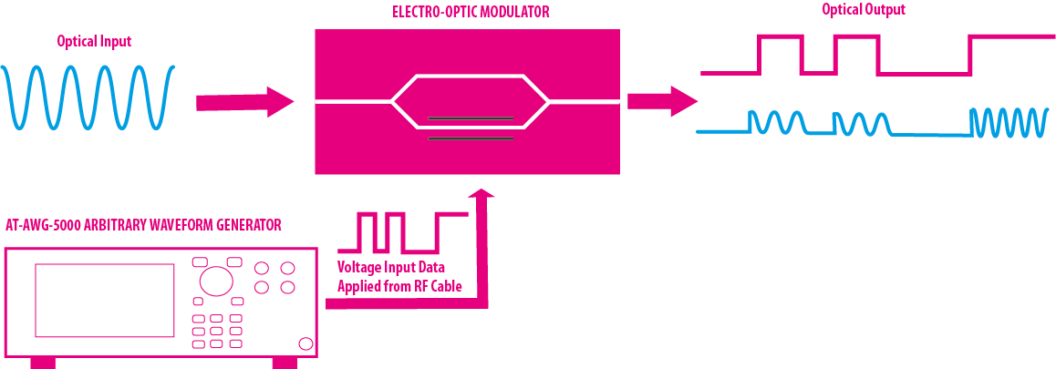
- Generation of high amplitude and high speed pulses to drive directly the electro-optic modulators.
- Generation of different kind of signals and pulses to make stimuli for quantum optics applications.
- Generation of pulses to drive the pulsed laser diodes.
Electro optic Modulator inside
Integrated-optical waveguides are able to guide light along a determined path analogue to optical fibre. The waveguide consists of a channel with higher refractive index compared to the surrounding material.
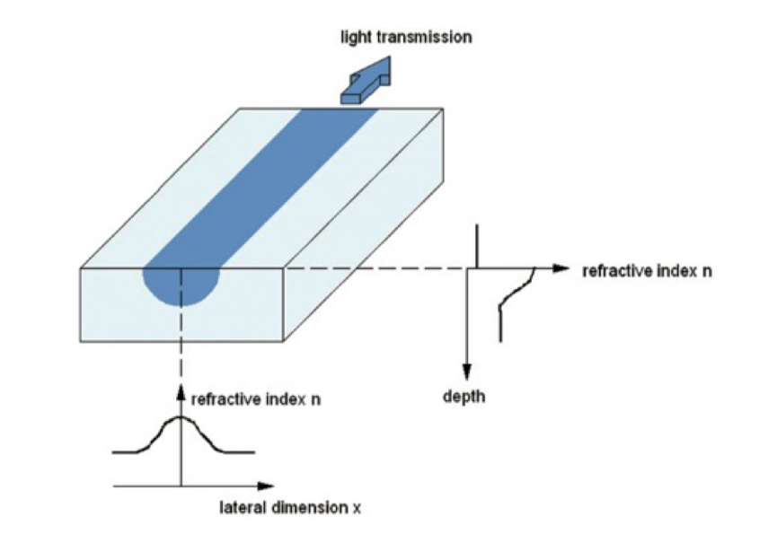
The light is guided by means of total internal reflection at the channel walls. Depending on the wavelength, substrate refractive index, refractive index difference, width and depth of the channel, one or more transverse oscillation modes can be excited.
The single mode operation is of great interest since it is essential for the function of many integratedoptical elements. Integrated-optical elements are usually provided with optical fibres particularly in optical communication technology.
The linear electrooptic effect, also known as Pockels-Effect, is a second order non-linear effect, consisting in the change of the refractive index of an optical material if an external electric field is applied. The amount of change in refractive index is proportional to the electric field strength, its direction and the polarisation of the light.
The preferred material for the fabrication of integrated-optical modulators is Lithium niobate (LiNbO 3 ).
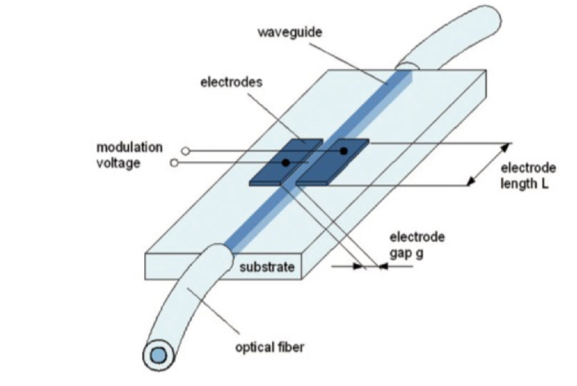
If an electric field is applied to a waveguide using electrodes of the length L, the refractive index changes in the area between the electrodes, giving a phase shift of the guided light. The phase shift is linear to the applied voltage.
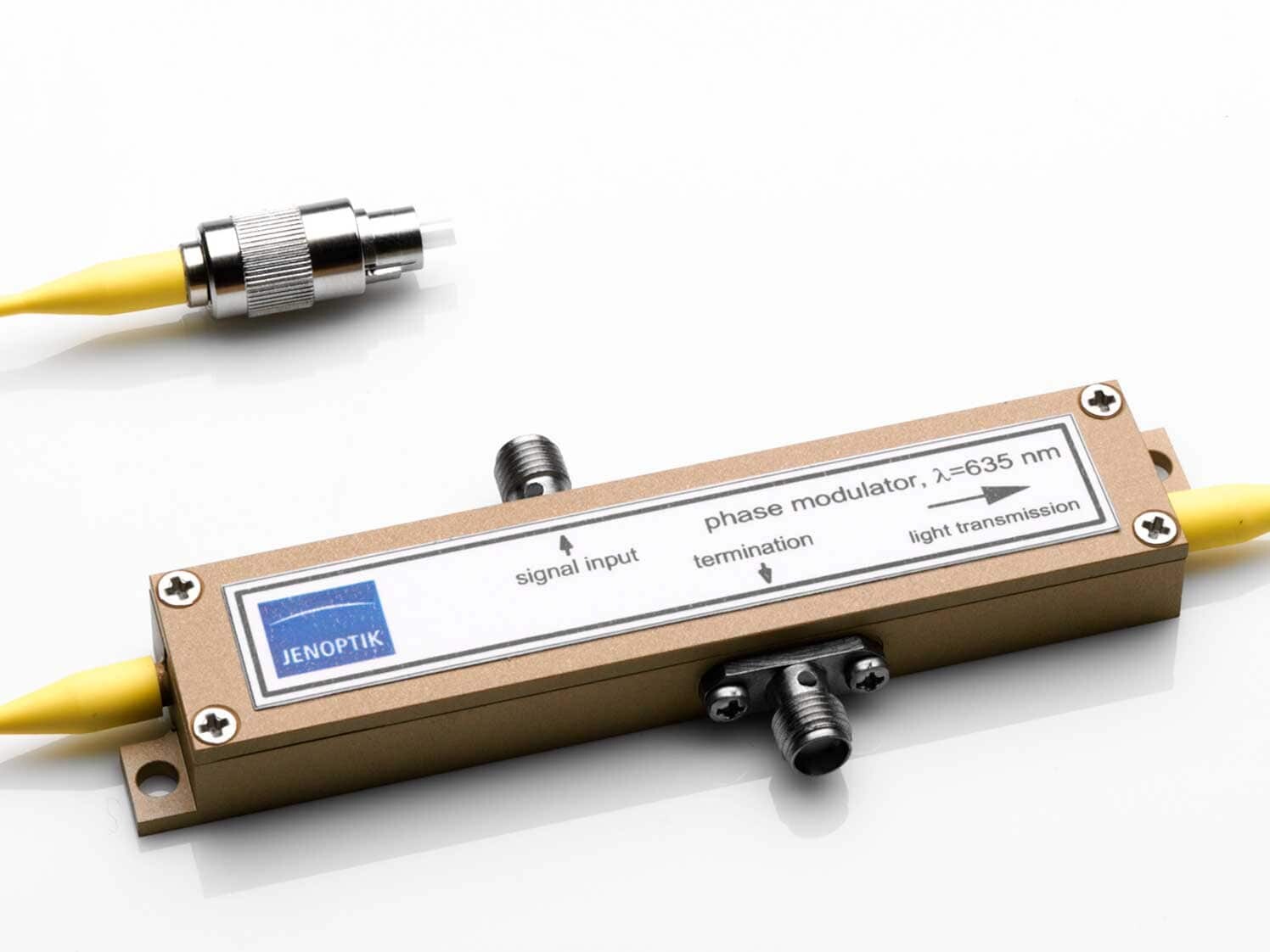
This typically amounts to a few volts. For longer wavelengths it is higher than for shorter ones at a given electrode geometry. For example it can be expected to be 3 V in the red (635 nm) and 10 V in the telecommunication wavelength range (about 1550 nm).
Due to the very fast electrooptic response, the low control voltages and the use of sophisticated electrode geometry, it is possible to achieve modulation at frequencies in the gigahertz range.
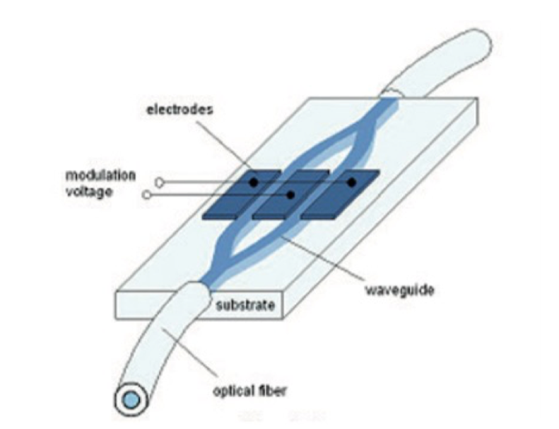
A phase modulator is inserted into an integrated Mach-Zehnder interferometer to form an amplitude modulator.
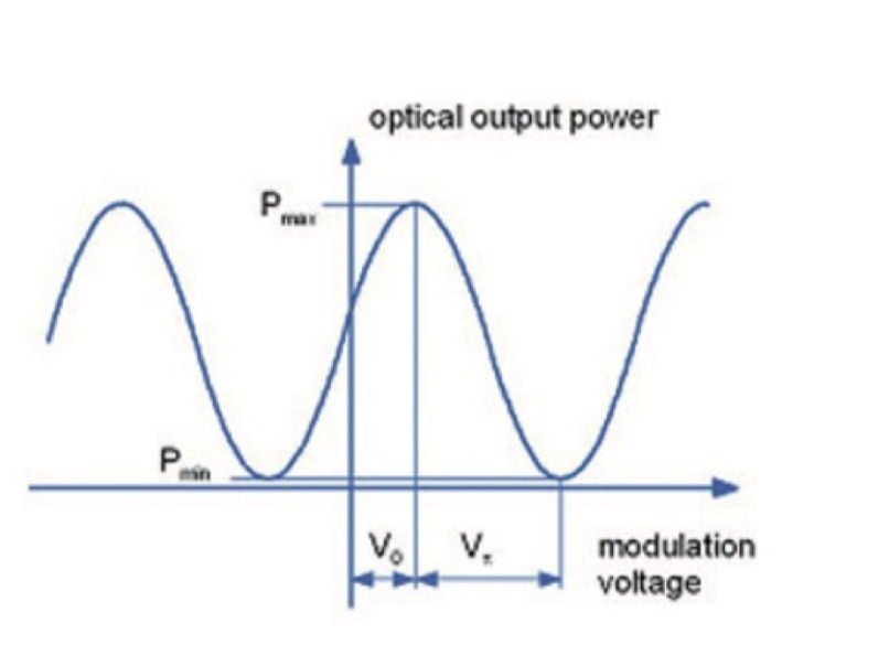
Applying a voltage leads to a relative phase difference between the branches, which causes a change of the output power at the device output by means of interference. So the device transmission can be controlled between a minimum and a maximum value (P min to Pmax ).
A relative phase difference of π is needed for switching from on to off state or vice versa. The needed voltage is called the half wave voltage Vπ of the amplitude modulator.
Due to the push-pull operation the half wave voltage of an amplitude modulator is the half of that of a phase modulator with equal electrode length. For example it can be expected to be 1.5 V in the red at 635 nm and 5 V in the telecommunication wavelength range about 1550 nm.
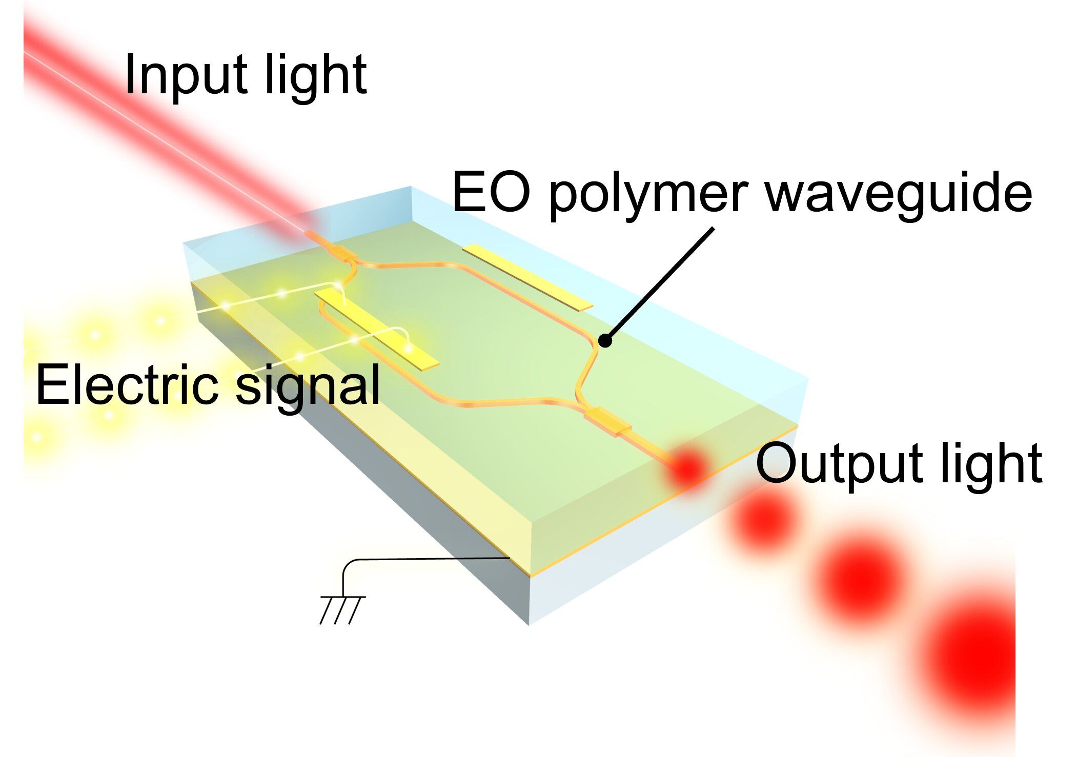
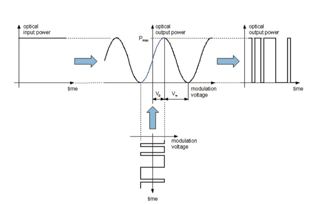
Applying a RF signal as modulation voltage to the electrodes, this electrical input is translated into an amplitude information.
This amplitude output depends on the voltage magnitude and shape, thus related to the position of the modulators operation point. The figure depicts the transmission of a binary pulsed electrical input into a binary optical output signal. If the voltage levels would not be correct, that is that the voltage is too high or the offset is not correct the modulator will react with non correct optical output levels in binary operation or with higher harmonics in analog operation.
Pulsed Laser
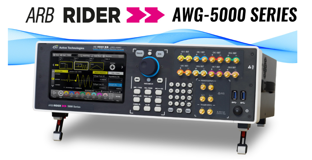
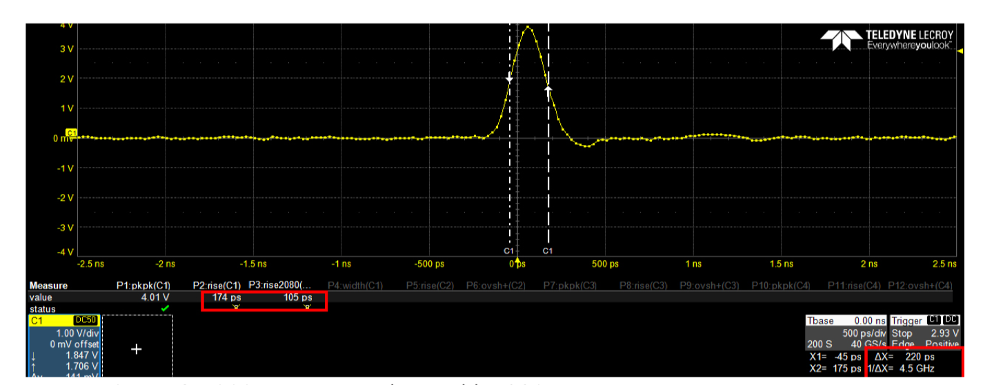
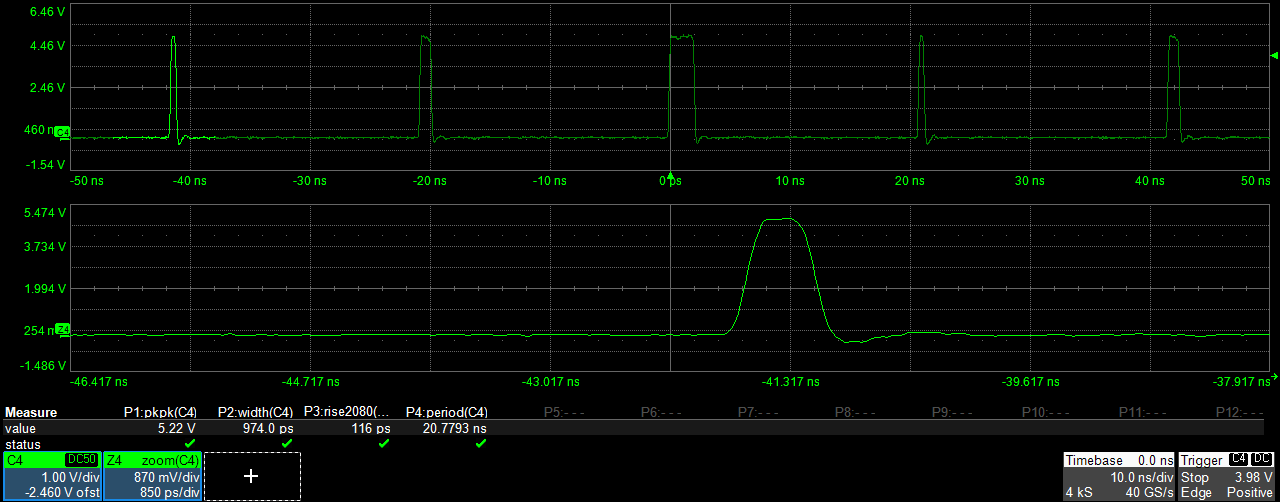
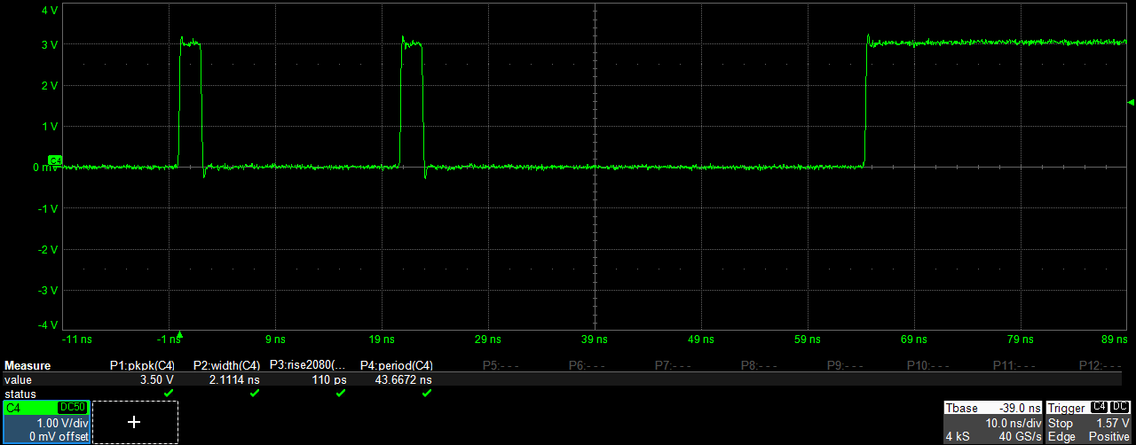
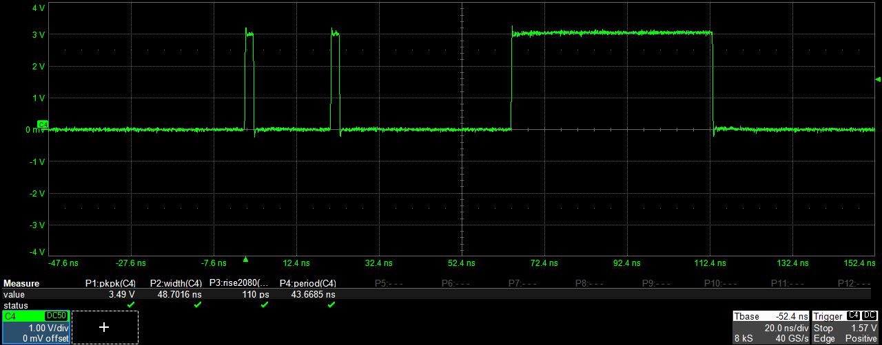
The Arb Rider AWG-5000 Arbitrary Waveform Generators allows you to create the modulation voltage by generating very narrow pulses (the minimum pulse width is 230 ps) with up to 5 Vpp amplitude.
The high amplitude output signal, combined with 110 ps of rise/fall time (5 Vpp @ 2 GHz Bandiwdth), gives you the possibility to directly drive different types of electro-optical modulators without adding an external amplifier.
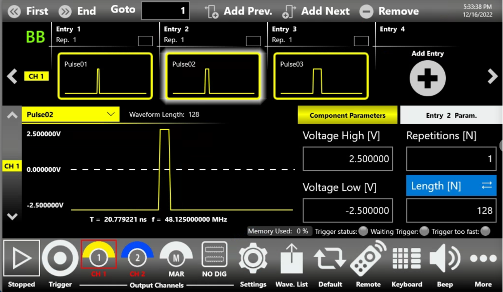
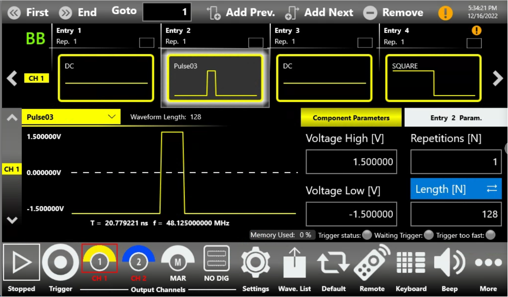
Thanks to the True-ARB User Interface, it is possible to easily generate different pulse’s shapes giving a more in depth control of optical output signal.
The Arb Rider AWG-5000 Series provides you an extremely flexible and high performance solution to generate all types of pulses or signals that are needed to meet today’s challenges in quantum optics, photonics and laser applications.
The new industry’s requirements and the development of new products, increase the demand for cutting-edge test-equipment instrumentation to satisfy the most demanding applications and the latest scientists’ ideas.
