AWGs for Digital Modulation
AWG-5000 Series Application Note – Digital Communications
Introduction
In the World of Radio Communications, signals are rapidly going to be all digital. This trend is mainly due to the better spectral efficiency that these have, compared to the analog ones. Signals central frequencies, spectral density and bands are increasing to satisfy the growing users demand; thus, devices are becoming more complex and critical in every operation they are requested to cope.
Here, the modern state of art Arbitrary Waveform and Function Generators can overcome that problem, providing a flexibility that has never seen before, giving to engineers a powerful instrument to produce all type of signals and digital modulation to test different stages of a transmission or reception chain, such as modulator, demodulator, mixer, filter, amplifier, Low Noise Amplifier (LNA), etc.
The different stages require different type of signals, here below we report some AWG application examples:
- Generation of stream of bits and trigger out signals (for next stages synchronization) to test the behavior of the coder system.
- Generation of a quadrature base-band signal supplied on one or two channels to test the transmission / reception of symbols with different parameters such as number of symbols, type of transmission filter, noise level.
- IF / RF signal generation to test mixer, IF filter, transmitter amplifier and the receiver stages.
Bit Stream Generation for digital modulation
Nowadays serial protocols are very diffused and used in many communication standards for the advantages they offer in terms of distance, noise immunity, and performance.
This type of communication consists in a stream of bits that the transmitter system parallelizes and converts in symbols.
Using Active Technologies Arb Rider AWG-5000 Series, it is possible to generate a stream of bits setting all the parameters such as frequency, amplitude, bit shape, etc.
Bit Stream Generation using the Sequencer
Using the AWGs, you can load the bit shape of the ‘0’ and the ‘1’ into memory and set the instrument to reproduce the bit ‘0’ or the bit ‘1’ executing a precise sequence or in function of an external input, generating a stream dependent on external source.
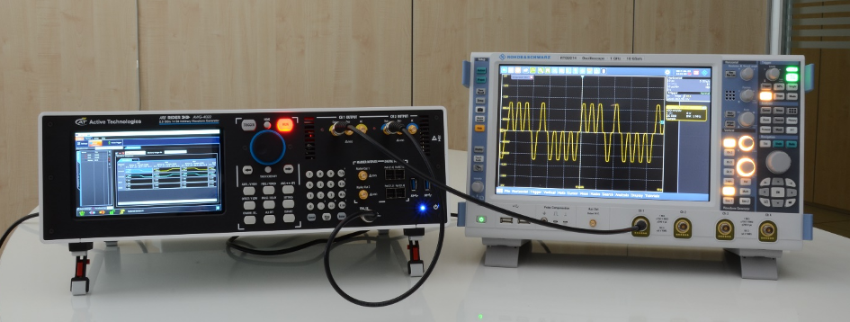
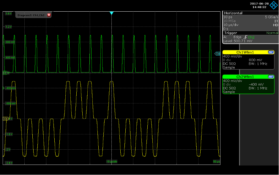
As example, we show a method to generate a bit stream using the Sequencer and the Marker channel. The channel one is used to generate the bit shape, for this example a Return Zero code and a pulse on each bit generated by marker-out. The channel two contains a Non-Return Zero code used to trigger the channel one. In this way, the definition of the pattern and the definition of the shape of the bit are uncoupled.
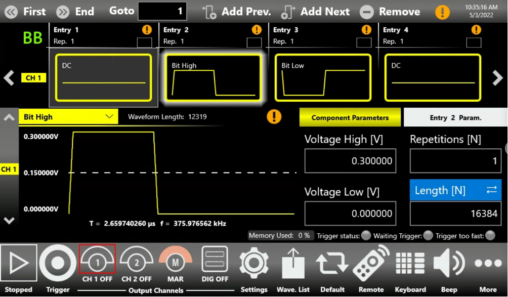
The sequencer of the channel one contains the bit shape for the bit “0” (waveform “Bit Low”) and for the bit “1” (waveform “Bit High”). The entries 2 and 3 are programmed to repeat infinite time and jump to the other waveform on the trigger in event: when a trigger rise edge occurs, the sequencer jumps from bit “0” to bit “1”, instead when the edge is falling, the sequencer jumps from bit “1” to bit “0”.
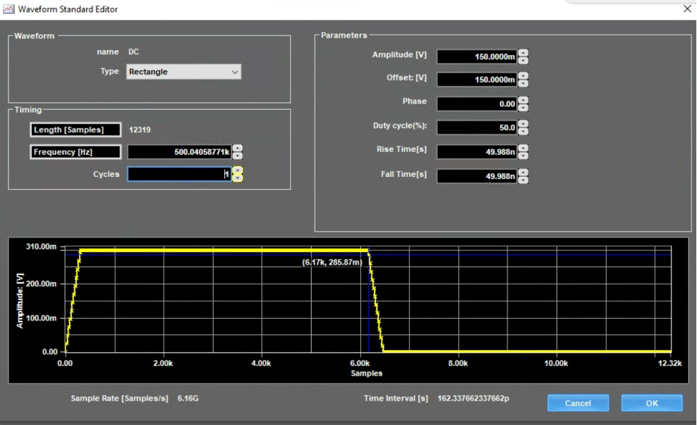
The second channel’s sequence contains the bits sequence we want to reproduce, in the example it has been created by queuing some DC levels with a value of 0 V for the bit “0” and 300 mV for the bit “1”, but is possible to load a file containing a bit sequence.
When you compose a bit stream, it is necessary to consider that the reception of the trigger-in takes 1.8 µs then to avoid errors you should respect a minimum bit period over 2 µs (500 kbps). The first two entries of the sequencer of the channel two are a delay and a pulse: the delay gives the necessary time to start the channel one and put it in wait state; the pulse gives the trigger to start the channel one. The first sequencer entry of the channel 1 is another DC level at 0V that acts as a “wait”, it is reproduced after the reception of the rising edge of the pulse from the channel two. The difference between duration of the first waveform of channel one (DC level at 0) and the pulse waveform gives the skew necessary to ensure that the edge arrives before the waveform ends. This game of delay, pulse and wait state ensure the synchronization between the channels.
I-Q Generation
In modern digital communication, usually baseband signals consist of two digital signals called I (in-phase) and Q (quadrature) that are combined by modulator; this is the reason why to reproduce this kind of signals it is necessary an AWG with two synchronized channels.
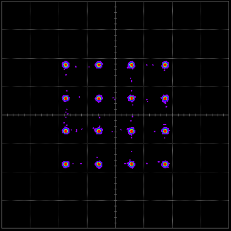
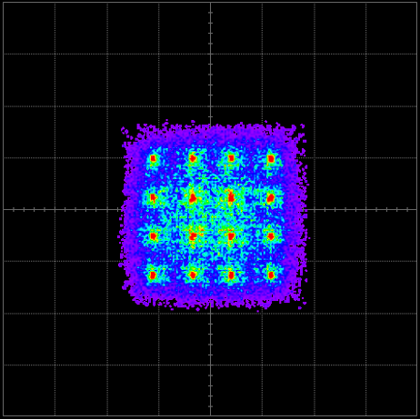
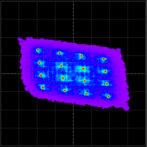
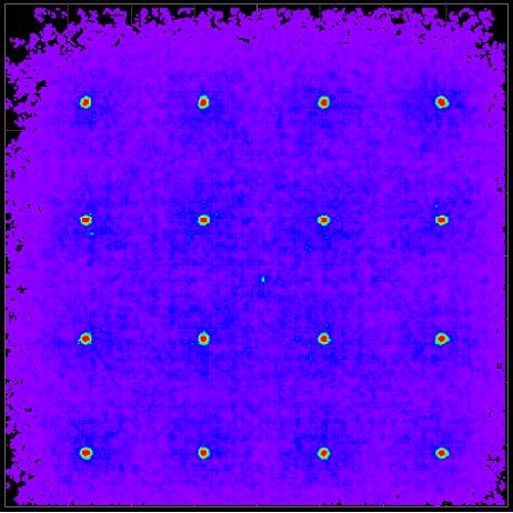
Although modern communications are based on digital technology, the output signals are analog ones and they have the typical problems of that domain: noise of the device that reduces the maximum SNR, non-linearity, quadrature errors, imbalances between I and Q channel that cause a distortion of the symbol constellations and a reduction of the theoretical performance.
Using a third-party software like NI Labview® or Matlab / Simulink®, it is possible to create different types of baseband signals with or without the imperfections said before and load the resulting waveform into the instrument memory.
Operating in this way, you can create and store many variants of the same modulation scheme and during the tests recall them to evaluate the system performance and find the best set of parameters.
Active Technologies Arb Rider AWG-5000 Series offers up to 8 analog channels, 4 marker ouputs and up to 32 digital outputs synchronous with the main channels in a single instrument; the use of mixed waveforms will permit to mark an event with a digital line synchronized with the analog waveforms sent to the Device Under Test.
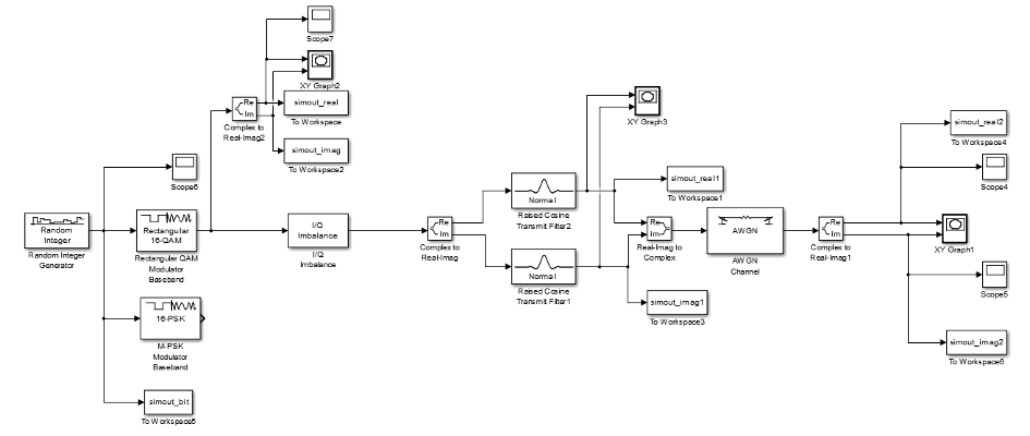
I-Q signal generation using Simulink blocks
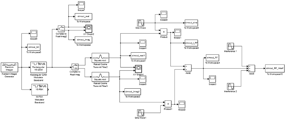
The following Simulink® example has been created to supply signals in different points of a transmission and receiver chain, here below you can read some practical applications:
Shaping filter improvement: the shaping filter is a filter matched between transmitter and receiver side that cuts the bandwidth to satisfy the requirement of spectral occupation and allows to avoid the Inter-Symbol Interference (ISI). The most commonly used filters are the raised cosine filter (usually in squared root form) and the Gaussian filter. Supplying the digital modulation before the filter (point 2), it is possible to test its behavior varying the set parameter or the type modulation.
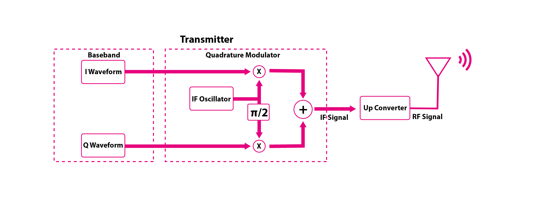
- Up-converter test: usually the base-band signal is modulated using 2 mixers that multiply it by the local oscillator signal. To test these circuits, it is necessary to supply the I and Q channel after the filter (point 3).
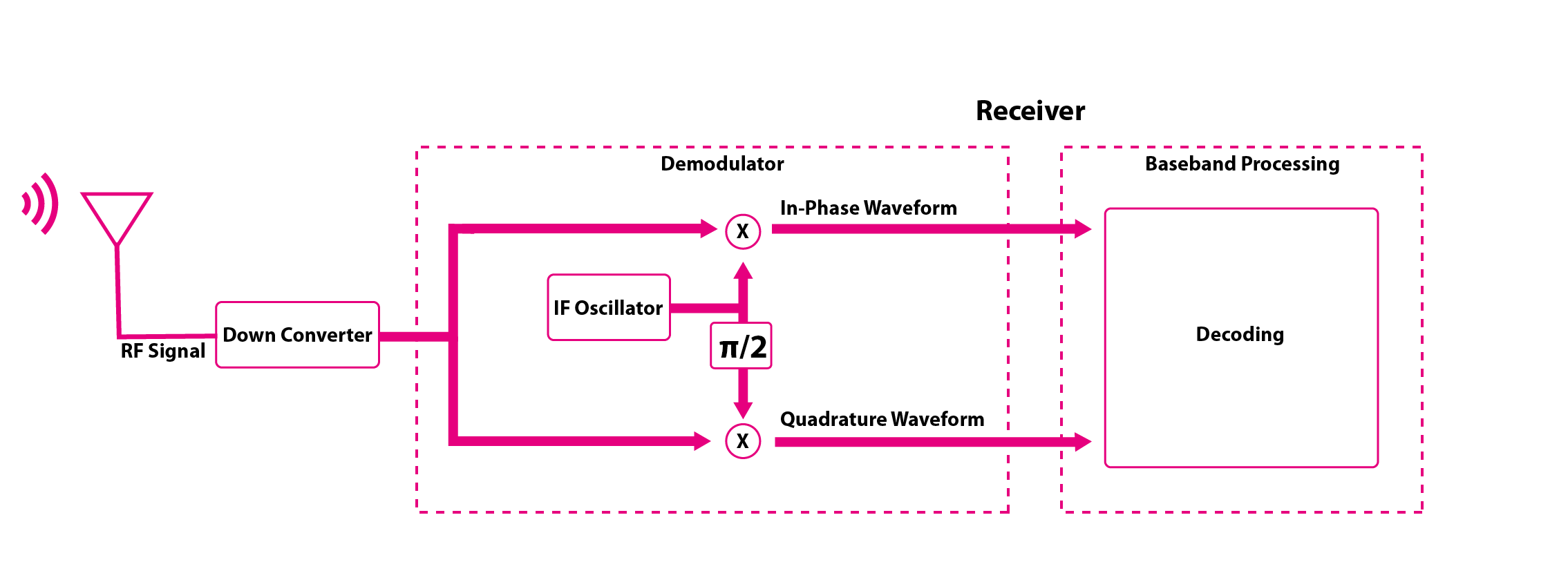
- Base-band receiving chain test: once the signal returns in base-band, some electronic circuits work to demodulate the signal.
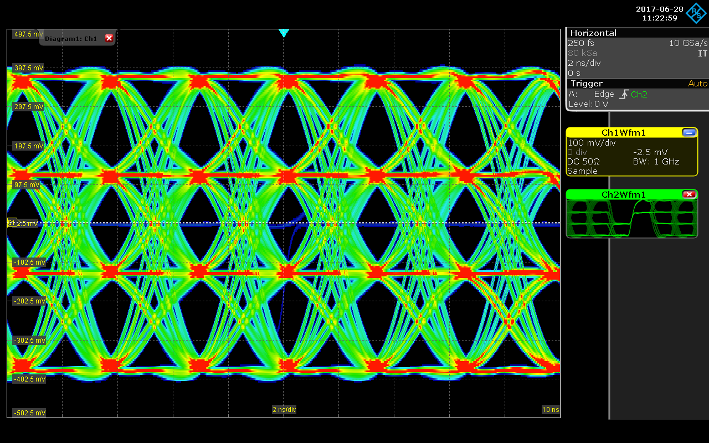
Supplying a digital modulated base-band signal (point 4) it is possible to test the response of the demodulator circuits at different level of Signal to Noise Ratio (SNR) or at different symbol rate.Moreover it is possible to test different parts like the symbol timing recovery, the matched filter and the decision maker.
- 1: Random number stream.
- 2(I), 2(Q): 16-QAM direct output (before shaping filter).
- 3(I), 3(Q): 16-QAM signal after impairment and Raised Cosine shaping filter.
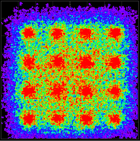
- 4(I), 4(Q): 16-QAM signal after AWGN channel.
- Simulink® provides several library blocks that allow to model a system simply combining them and setting their parameters.
In this document, we report as example the construction of a model to generate an I-Q baseband signal, adding a transmission filter, some impairment like I-Q imbalance, AWGN channel noise (or fading).
Finally the result is exported into Matlab® workspace and loaded into the instrument memory using a script that drives the instrument using the SCPI commands.
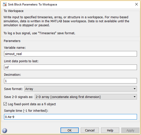
We suggest, when possible, to set the “Sampling Time” of all “To Workspace” blocks to the AWG sampling period, in the example it will be set to 162 ps (6.16 GS/s).
In this way, the generated array of samples will be directly compatible with the AWG architecture.
Unfortunately, not all Simulink blocks supports a decimal sample time, in this case the suggestion is to set the Simulink sampling time at 1 and set the “Simulation Time” at the number of samples that you want load into AWG.
IF / RF Generation
The I-Q signals can be combined using an external modulator that could add unwanted distortion, moreover the modulator should be replaced in case of changing the modulation scheme under analysis.
The direct RF/IF synthesis by means of an AWG can overcome the problems described above.
Using a software like NI Labview® or Matlab / Simulink® it is possible to create directly the RF/IF modulated signal adding the imperfections and finally loading the result into the AWG memory.
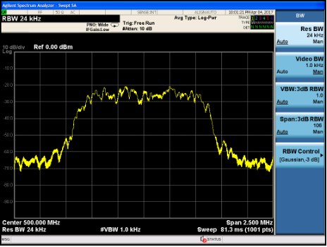
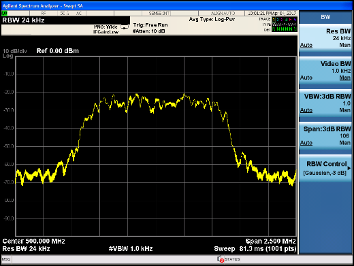
The Arb Rider AWG-5000 Series can generate in Baseband mode, RF modulated signals up to 2 GHz considering an oversample over 4 times to ensure a good spectrum quality signal.
Moreover the option called RF Mode allows the instrument to work at 12.32 GS/s sampling rate and it is possible to create RF modulated signals up to 6 GHz.
RF signal generation using Simulink blocks
With the described Simulink model, it is possible to generate modulated signals in different stages of the transmission and the receiver chain:
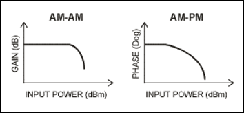
- Transmitter RF amplifier test: in quadrature modulation, the linearity of RF amplifier is very important because non-linearity causes additional unwanted modulation such as AM/AM and AM/PM conversion.
Usually the RF amplifier characteristics are measured using a VNA that supplies a sine wave and analyses the response.
On the contrary the AWG can supply the modulated RF signal directly to the amplifier with the advantage to test it in real operating conditions (point 5 of the Simulink model).
The final result depends on the operating point of the devices and on the thermal effects, then a measurement with a sine wave may give results different from the real condition in which the amplifier will operate. - Receiver RF section test: the RF section is composed mainly by filters, Low Noise Amplifier (LNA), mixer and carrier recovery circuits; this section has to transfer only the desired signals.
In this Simulink example (point 6 of the model) we added two interfering signals at a different distance from the carrier to test the receiver performance. - Receiver chain test: the RF modulated signal can be used to test the entire receiver chain, supplying the modulated signal with different impairment and observing the performance of the receiver (point 6 of the model).
- Equalizer test: modern receivers can switch among multiple antennas in function of signal power or combine the multiple signals to obtain the best possible signal.
The AWG channels can be loaded with the same RF signal but with different amplitude or phase; in this way, it is possible to test the equalizer performance.
For this kind of test, it can be useful the AWG sequencer, because it allows to create a waveform
This Simulink model is an extension of the previous one: after the baseband section, we added two multipliers to simulate the mixers and two sine functions to simulate the local oscillator.
Moreover, after the RF generation section, we added others two sine functions to simulate interfering signals near the carrier.
Generate RF Wireless Signals with RF Mode
The AWG-5000 Series Arbitray Waveform Generator can work in Baseband mode with a Real Time sampling rate of 6.16 GS/s or in RF-Mode with an Interpolated sampling rate of 12.32 GS/s.
Using the RF-Mode, it is possibile to generate RF wireless signals and modulated pulses up to 6 GHz.
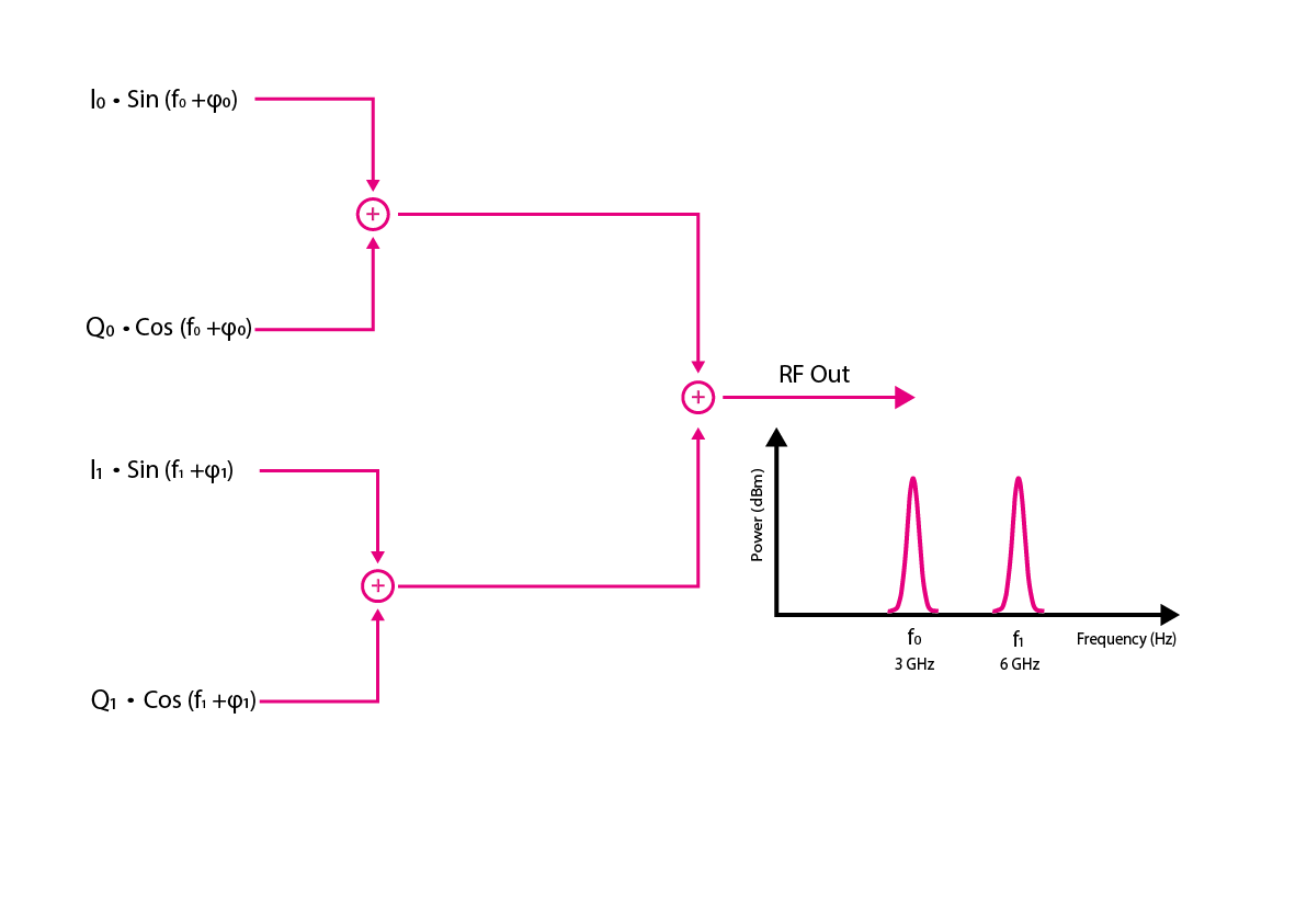
The internal modulator and up-converter allows you to create RF signals with one or two carries (Single and Double Carrier mode); using this mode it is possible to switch easily between two frequencies and add impairments in real-time like amplitude and skew between the different.
